May 14, 2015, by Laura Pasquale
Feedback control of unsteady flows: using plasma to improve aircraft aerodynamics
Flow control is a fast growing multidisciplinary science aimed at altering a natural flow state into a more desired state, which could be chosen depending on control objectives (e.g. manipulation of flow separation and flow reattachment, drag reduction, noise suppression, etc.). It incorporates essential and non-trivial elements of fluid dynamics, numerical methods and control theory and this is why there has been an increased participation of researchers in apparently disparate fields. The aim of integrating active flow control strategies over the aircraft’s control surfaces is to improve the aircraft aerodynamics. There are several reasons why this is desirable: for example, it is possible to reduce skin-friction drag up to 25% [Collis & Joslin 2004]. A similar reduction in terms of both aircraft fuel consumption and CO2 emissions can be expected through this technology, which also brings the additional benefit of the reduction of flow noise. The feasibility of increasing efficiency and simplifying hydraulically actuated systems (e.g. high-lift systems) is very appealing if one considers that even a 1% saving in the world consumption of jet fuel is worth about 1.25 million dollars a day of direct operating costs. Therefore, reducing the average overall drag by just a few percent could save several billion dollars annually, yielding significant environmental benefits as well as enabling increased speed, range, and endurance.
To this end, considerable efforts have been directed towards developing and evaluating control strategies for aerospace applications over the past three decades. However, active flow control technologies have not been adopted in commercial aircraft yet, despite the intensive research currently being carried out. This is due to the inherently chaotic nonlinear nature of the leading physical process and to the difficulty in monitoring or estimating the turbulent flow status and parameters accurately. Moreover, communication barriers due to the disparate skill sets have historically led to slow progress; consequently, there are several unsolved key issues which need to be addressed.
Flow control strategies can be categorised in two different ways:
- based on the type of actuation, which can be passive (steady) or active (unsteady);
- based on the actuation system response to changes in the flow, i.e. open-loop (feedforward) or closed-loop (feed-back) control.
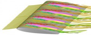
The optimised shape of an aircraft wing, riblets, steady blowing/suction as well as the evolutionary design of the skin of fish are all examples of passive flow control. For instance, the tubercles of the humpback whale flipper may function to generate vortices by excitation of flow to maintain lift and prevent stall at high angles of attack (see Figure 1).
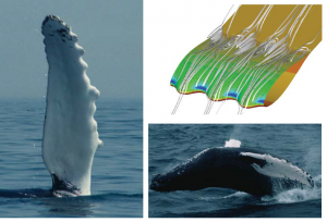
Figure 1: Humpback whale flipper leading edge tubercles (left); Pressure contours and streamlines at = 10° for NACA 63021 with leading edge tubercles (top right); breaching humpback whale showing relative size of the flipper (bottom right). Images from Fish & Lauder 2006.
Passive control is inherently open-loop, as it cannot respond to changes in the flow state The main advantage of passive actuation, such as riblets or compliant surfaces, is simplicity. Passive control techniques are indeed lighter, less expensive and easier to maintain, compared to the active ones, thereby making them the only ones that have been used in real-world applications so far. However, there is only a very limited range of operating
conditions over which passive control strategies may be effective. Furthermore, there may even be cases in which passive control degrades system performance, since the control itself could initiate new instabilities [Bechert & Bartenwerfer 1989]. The reason for this is due to the fact that passive control techniques produce a steady feedforward action, which does not take into account eventual changes in the physical system to be controlled. This allows passive methods for successfully targeting only known, constant disturbances. Active control techniques are thus needed in order to face more realistic operating conditions.
Active open-loop strategies assume exact knowledge of the system and do not respond to changes in the flow state or unknown disturbances, as actuator parameters are set off-line at the design stage. Therefore, if disturbances that are not accounted for in the model are present, the controller will in general fail. Compared to open-loop approaches, closed-loop controllers can reduce the in influence of disturbances and enhance aerodynamic performance with less control effort, since they use real-time information from the system, which is not taken into account a priori, thereby making it more robust to deviations from the assumed model.

Figure 2: Airbus A320 flow solution. Image from adg.stanford.edu.
On the other hand, the inherently chaotic nonlinear nature of the flow dynamics and the high dimensionality of the numerical flow field model (see Figure 2) lead to many issues in accurately modelling unsteady fluid systems and, at the same time, designing an effective and efficient control scheme that relies on such a sufficiently accurate model. Indeed, the reconstruction of the high-dimensional flow field data out of limited measurements is not feasible for practical real-time applications. In particular, one has to consider that feedback controllers compute the control signals on-line, based on sensor measurements and control law, which is designed upon the assumed model. This is a very challenging task from a computational point of view, as the equations describing the flow dynamics cannot be solved analytically and their numerical approximation yields a very high-dimensional system of equations (104 – 106 state variables, depending on the number of mesh nodes). Furthermore, turbulence is a multi-scale phenomenon with significant dynamics evolving relatively far from the wall, where sensors and actuators are located (e.g. along the aerofoil). Consequently, most of the flow states are unobservable and uncontrollable. Thus, a control-oriented model mainly needs to capture the essential dynamics, that is the relation between inputs and outputs and their in influence on the quantity of interest” (which depends on the desired target state), while taking into account both computational cost and model accuracy, according to control objectives.
In view of the above, the introduction of reduced-order models (ROMs) is of particular interest in flow control problems. A ROM can be computed, using either simulation or experimental data, through a projection of the system equations onto a lower-dimensional subspace, with the aim of capturing the system dynamic response by retaining only few fundamental dynamic modes, in order to make the real-time computations feasible. Such a simplified model is thus suitable for the design of both: a robust, reduced-order, feedback controller, which will automatically compute the electrical input signal, to be converted to a physical quantity by mean of an actuator; a reduced-order observer, which will estimate the relevant flow field from few measurements. This is pivotal in order to enable a full and efficient air flow regulation over the aerofoil.
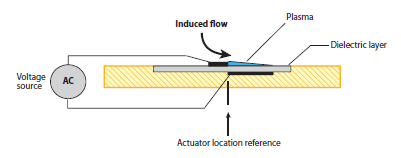
Figure 3: Dielectric barrier discharge actuator. Image frome Corke, Enloe & Wilkinson 2010.
To this aim, among all the different types of actuation, a new and original technology using non-thermal surface plasmas is in under intensive research. These plasma devices, which usually consists of two electrodes separated by a dielectric material, aim to manipulate the air flow by using a discharge-induced electric wind. Aerodynamic flow control based on surface dielectric barrier discharge (DBD) devices, whose schematic is shown in Figure 3, has seen a significant growth in interest in recent years, as they have no moving parts, have an extremely fast time-response as well as low mass and low input power. This specific DBD configuration used for plasma actuators consists of two electrodes, one uncoated and exposed to air and the other encapsulated by a dielectric material; hence, this configuration is referred to as a single dielectric barrier discharge (SDBD). Electrodes are supplied with an AC voltage that, over a certain threshold, causes air over the covered electrode to weakly ionise. In the classic description, ionised air is a plasma, which is why these devices are referred to as plasma actuators. The aim of using an ionic wind is to accelerate the air flow very close to the wall, in most cases tangentially, in order to modify the air flow profile within the boundary layer. In the presence of the electric field produced by the asymmetric electrode geometry, the ionised air results in a localised body force vector field, which is directed downstream in most aerodynamic control applications and acts on the overlying neutrally charged air. The mechanism of flow control exploited by these devices is through this resulting body force vector field that couples with the momentum equations describing the neutrally charged fluid dynamics.
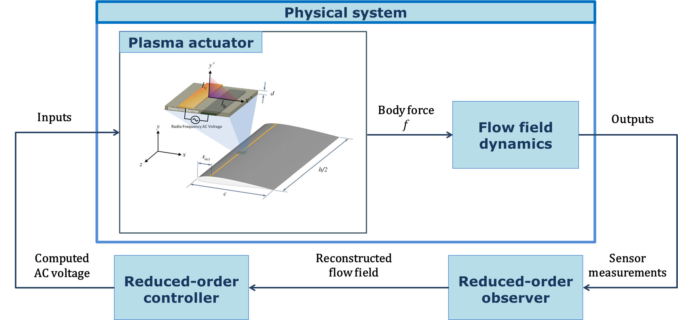
Figure 4: Schematic of the closed-loop system. Image of the actuator from Cho & Shyy 2011.
The plasma actuator AC voltage can be used as a control input so that the generated force directly affects the turbulent flow over the wing. Both actuators and sensors can be easily placed on an aerofoil and their position heavily affects the controllability and observability properties of the system, and thus the control effectiveness. The sensors are usually located further downstream than the actuators, in order to detect changes in the flow state that are induced by changes in the control inputs. The output measurements are used by the observer, which reconstructs the part of the relevant flow field that is not detected by the sensors. The controller will then compute the new input signals on-line, based on the knowledge of the reconstructed flow state, in order to lead the system towards the desired objectives, e.g. reduction of drag, noise and flow separation. The updated input voltage is fed to the actuator, that will then convert it to a new force, which, in turn, will generate new outputs. The schematic of the closed-loop system is shown in Figure 4.
The effectiveness of the control scheme strongly relies on how accurately, and at the same time “cheaply”, the model captures the input-output behaviour of the physical system to be controlled. Unfortunately, how to efficiently model the parametric (e.g. parametrised by the angle of attack and the Reynolds number), unsteady, chaotic and intrinsically nonlinear dynamics of controlled fluid systems is still an open issue.
No comments yet, fill out a comment to be the first


Leave a Reply