August 19, 2014, by Luca Bertola
How Do Aeroplanes Stay Stable in the Sky?
Many years of testing and implementing advanced technologies have passed, but most people still wonder how an airplane flies despite air travel representing such a popular mode of transport in the 21st century.
In 1895 Lord Kelvin stated that ‘heavier-than-air flying machines are impossible’. It is safe to say that he has been proved definitively wrong due to the myriad of ‘heavier-than-air’ variations of aircrafts flying all around the world. Therefore, how do huge objects like the Airbus A380, with a maximum take-off weight of 590 tons, take to the air?
The answer is hidden in the property of the fluids described by the Bernoulli theorem, which states that if the speed of the fluid is increased, the internal pressure will decrease. Now let’s consider an airplane wing section like the one represented in the Figure 1. Once the air flux encounters the wing it separates into two streamlines that flow above and under the wing respectively. Due to the particular wing shape the upper streamline accelerates, reaching a speed much higher than the lower streamline. This phenomenon causes a sharp reduction of the pressure above the wing and consequently a net force called lift that is large enough to sustain the airplane. However the flux deviations provoke another force, opposite to the motion, that the propulsion system has to compensate for to maintain the cruise speed. This process is well described by the Navier-Stokes equations which are the basis of all modern Computational Fluid Dynamics software.
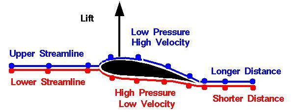
Figure 1 – Air flux around the wing section
So this is how the wings of an aircraft are used to generate aerodynamic forces able to carry the plane, but how does the plane maintain stability?
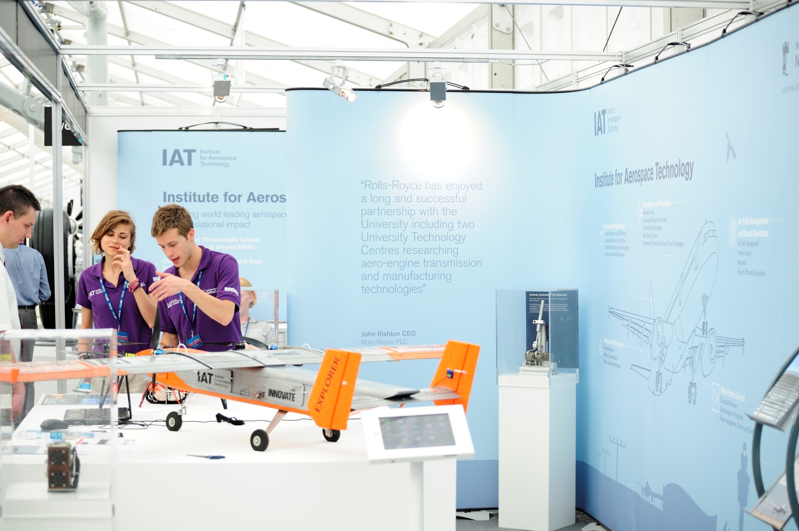
Every airplane has several surfaces that are used to control its movements during the flight. In order to better clarify which surfaces are we talking about see the picture of the INNOVATE team presenting its UAVs (Unmanned Aerial Vehicles) at the Farnborough Air-show 2014 in Figure 2. The ailerons are movable surfaces on the wing edges that move in opposite direction to control the roll angle (rotation around the motion direction). The rudder is the vertical surface on the tail that controls the rotations around the yaw axis (nose right-nose left), while the stabilizer is the horizontal surface on the tail to control the movements around the pitch axis (nose up –nose down).
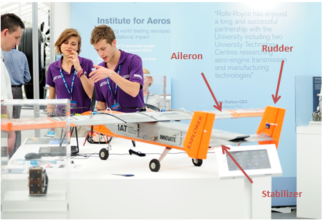
Figure 2 – Fixed Wing UAV at Farnborough Air-show
When the pilot decides to execute a manoeuvre it is not only necessary to get a rapid response, but also to maintain stability.
You may have noticed that the airplane wings are bent upward for down-mounted wings (when the wings join at the airplane’s belly) or downward for up-mounted wings (like the UAV in Figure 2). With the wings inclined by an angle called dihedral angle, the lift force has a component that points the fuselage of the airplane. As soon as a roll disturbance occurs, the horizontal components of the lift change their modules to generate a torque that restores the initial position. Civil aircrafts need this passive roll control, since none can conceive a pilot correcting the trajectory all the time using the ailerons, especially in those trips that last many hours. On the contrary, models like our UAV in Figure 2 do not need to keep the roll position stable for long travel, consequently it is not mandatory for their wings to have a dihedral angle.Figure 2 – Fixed Wing UAV at Farnborough Air-show
In a similar way, the rudder provides the stability around the yaw axis. The rudder is made with a symmetric profile that does not produce any force if it stays parallel to the flux lines. However, when a disturbance rotates the airplane around the yaw axis, an angle appears on the rudder and a lift force tends to bring the airplane back in the equilibrium position.
The stability on the longitudinal plane is the most complex and the most important to analyse since all the forces (lifts, drags, thrust, weight, and aerodynamic momentums) are acting on this plane and since they vary with the inclination of the aircraft (and thou its actual position on the longitudinal plane). To define the UAV performance during the flight at the design stage, we performed the stability analysis. Figure 3 lists all the forces that are included in the following equilibrium equation.
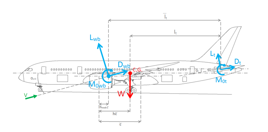
Figure 3 – Forces and torques on the longitudinal plane
Considering that the distances along the vertical axes are approximately zero, the angles are very small, the contribution of the drag is small and the aerodynamic moment of the tail is negligible compared with the moment of the wing equation can be easily linearized. It is better to state the stability conditions on the longitudinal plane without going through the mathematical passages that lead to them:
- The aerodynamic momentum at a zero angle of attack must be positive to grant the existence of a stability condition. In practice this means that at a zero angle of attack a positive aerodynamic torque is generated to bring the airplane to the rated positive stable angle.
- The neutral point (the point where all the aerodynamic forces can be imagined to act), must be behind the centre of gravity of the airplane. This means that any disturbance that varies the pitch angle (all the disturbances can be thought as torques acting on the centre of gravity), is balanced by an aerodynamic torque acting on neutral point.
The distance between the centre of gravity and the neutral point is called the margin of stability. The higher it is the more stable the airplane, but manoeuvrability becomes more difficult. The best margin of stability has to be chosen as the best compromise between stability itself and manoeuvrability.
Our UAV has a positive aerodynamic momentum coefficient of (where the aerodynamic coefficients are a non-dimensional way to express the respective aerodynamic forces) and a margin of stability. The margin of stability is expressed as a non-dimensional number because each distance on longitudinal plane is divided by the length of the cord. To detect letters on the ground and to deliver the payload on them we decided to favour the stability rather than the manoeuvrability. This, among other things, lead the INNOVATE team to successful payload deliveries, such as the one shown in this video link:
https://www.youtube.com/watch?v=54lPPiwfG0A
To learn more about the INNOVATE project, visit our website (www.nottingham.ac.uk/innovate) or follow us on Twitter (@UoNInnovate).


Great to see the next generation of aerospace engineers learning their trade!
Thank you for the interest you are showing in our activities!