October 14, 2013, by Dominic Foo
What is Water Pinch Analysis?
In this What is? series, we invite experienced researchers to write about their area of research, but in more general terms than they might normally do.
This article, entitled What is Water Pinch Analysis?, is written by Prof. Dominic Foo
If you would like to contribute, then please let me know (Graham.Kendall@nottingham.edu.my) and we can discuss how best to go about it.
Anybody wishing to contact the author of this article should go to about the author.
With the rising cost of fresh water and increasingly stringent environment regulations, there is a need to maximise the efficiency of the use of water, while minimising the generation of waste. Apart from the mismanagement of natural resources such as the over-extraction of water resources, the rising of population growth, water pollution problems and climate change also increase water stress. Hence, efficient use of various resources such as water, utility gases and solvents in industry is now recognized as being vital to achieving sustainable development. Fortunately, many problems pertaining to resources conservation in industrial process plants share common features, which allow them to be handled using a common family of systematic techniques known collectively as process integration. Two main categories of techniques developed for process integration are pinch analysis and mathematical optimisation. This article explains how pinch analysis is used for a common resource conservation problem on water minimisation, or water pinch analysis in short.
Fundamental principles
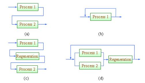
Conventionally, process integration or more specifically, pinch analysis (the graphical approach of process integration) is known to engineers as an energy saving tool (Linnhoff et al., 1982, 1994; Smith, 2005; Klemeš et al., 2010). With recent development of process integration tools, resource conservation can now be handled efficiently with process integration techniques. In the context of process integration, material reuse refers to the scheme where effluent from one process unit is channelled to another unit and does not re-enter the unit where it has been previously used; while recycle allows the effluent to re-enter the unit where it has been previously used (Wang and Smith, 1994). When the maximum potential for direct reuse/recycle is exhausted, the effluent may be sent for regeneration in an interception unit (a purification unit that improves its quality) in order for further reuse (Figure 1.12(c)) or recycle (Figure 1.12(d)). These schemes are illustrated in Figure 1.
Figure 1 Strategies for resource conservation: (a) direct reuse, (b) direct recycle, (c) regeneration-reuse, (d) regeneration-recycling
In order to carry out a resource conservation exercise, we will need to identify material sinks (units that require a valuable resource) and sources (units that produce resource of interest). Most often, the latter is found in the outlet stream of a process unit. On the other hand, a process sink refers to a unit where a resource is consumed (Figure 2).
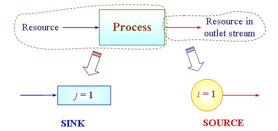
Figure 2 A material sink and source
Example of water minimisation
A special case of resource conservation is water minimisation, introduced by Wang and Smith (1994). A simple example on water minimisation is shown here. Figure 3 shows the process flow diagram of a Acrylonitrile (AN) production (El-Halwagi, 1997). Products from the reactor is cooled and partially condensed. The reactor off-gas is sent to a scrubber that uses fresh water as the scrubbing agent. The bottom product from the scrubber is separated into the aqueous layer and an organic layer in a decanter. The organic layer is later fractionated in a slightly vacuumed distillation column that is induced by a steam-jet ejector. There are two water sinks (units that require water feed) in this process, i.e. boiler feed water (BFW) and feed stream to the scrubber; and four water sources (units that produce water) which include the off-gas condensate, aqueous layer from decanter, distillation column bottoms and steam-jet ejector condensate. Ammonia (NH3) is the main contaminant in this process. The limiting water data (maximum concentration and minimum flowrate) for each process unit is given in Table 1.
Table 1 Limiting water data for AN production
|
Water sinks (SK) |
Flowrate |
NH3 composition |
|
|
j |
Stream |
FSK (kg/s) |
CSK (ppm) |
|
1 |
BFW |
1.2 |
0 |
|
2 |
Scrubber |
5.8 |
10 |
|
Water sources (SR) |
Flowrate |
NH3 composition |
|
|
i |
Stream |
FSR (kg/s) |
CSR (ppm) |
|
1 |
Distillation bottoms |
0.8 |
0 |
|
2 |
Off-gas condensate |
5 |
14 |
|
3 |
Aqueous layer |
5.9 |
25 |
|
4 |
Ejector condensate |
1.4 |
34 |
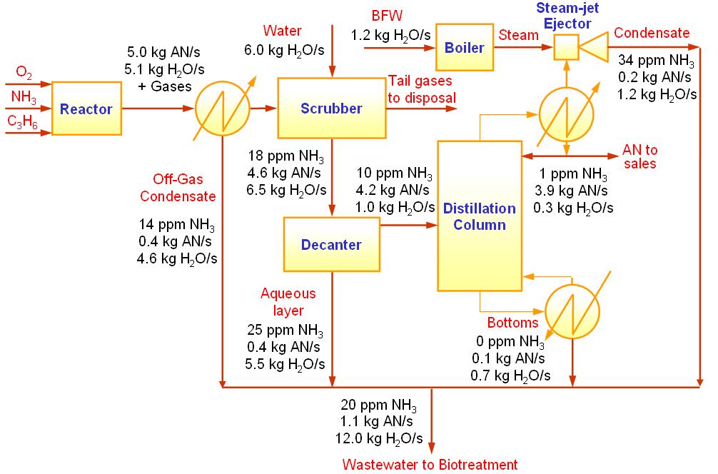
Figure 3 The AN process
To locate the minimum water flowrates in this process, the engineer can either plot the graphical targeting tool known as the material recovery pinch diagram (El-Halwagi, 2006, Figure 4) or carry out the algebraic approach of material cascade analysis (Foo, 2012, Table 2), which can be automated in a spreadsheet e.g. MS Excel. Table 2 show that the fresh water (FFW) and wastewater discharge (FWW) flowrates of the AN process have been reduced significantly to 2.06 kg/s and 8.16 kg/s. This corresponds to a reduction of 70% and 38% respectively (original flowrates are obtained from the sum of individual flowrates in Table 1). A pinch composition is found at the composition of 14 ppm, which represents the most constrained area in the reuse/recycle network where maximum recovery may be achieved. Figure 4 also shows that 4.9 kg/s (FREC) of water is being recovered between the sources and the sinks. The resulting reuse/recycle scheme is shown in Figure 5.
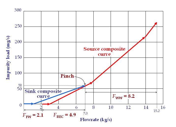
Figure 4 Material recovery pinch diagram
Table 2 Material cascade analysis for AN case
|
Ck (ppm) |
Σj FSKj (kg/s) |
Σi FSRi (kg/s) |
Σi FSRi – Σj FSKj (kg/s) |
FC, k (kg/s) |
Δmk (mg/s) |
Cum. Δmk (mg/s) |
|
FFW = 2.06 |
||||||
|
0 |
1.2 |
0.8 |
-0.4 |
|||
|
1.66 |
16.57 |
|||||
|
10 |
5.8 |
-5.8 |
16.57 |
|||
|
-4.14 |
-16.57 |
|||||
|
14 |
5 |
5 |
0.00 |
|||
|
0.86 |
9.43 |
(PINCH) |
||||
|
25 |
5.9 |
5.9 |
9.43 |
|||
|
6.76 |
60.81 |
|||||
|
34 |
1.4 |
1.4 |
70.24 |
|||
|
FWW = 8.16 |
8156865.51 |
|||||
|
1000000 |
8156935.76 |
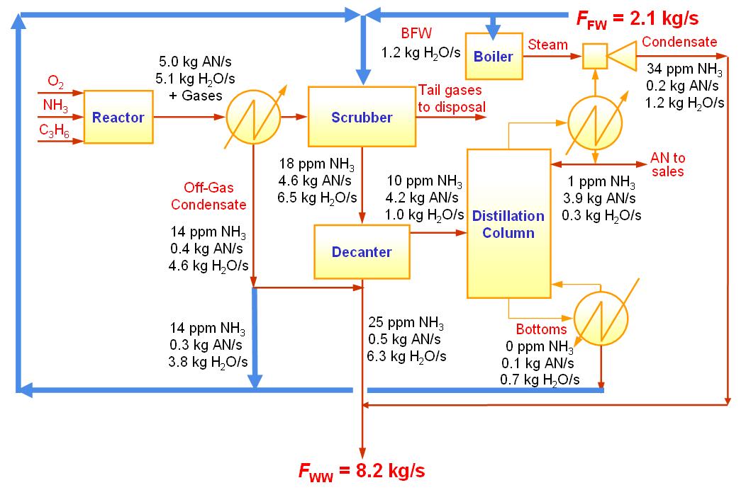
Figure 5 Water network design for AN case
Conclusion and further reading
This paper shows how resource conservation can be handled efficiently by process integration. By setting the minimum fresh resource and waste targets in prior, engineers can now identify the maximum possible saving that can be achieved in a reuse/recycle system. Apart from the water minimisation example given here, other resource conservation cases (e.g. hydrogen and utility gas recovery, property integration) can also be handled with similar techniques (Foo, 2012). Besides, similar tools have also been developed for batch processes (Majozi, 2009; Foo, 2012).
References
El-Halwagi, M. M. 1997. Pollution Prevention through Process Integration: Systematic Design Tools. San Diego: Academic Press.
El-Halwagi, M. M. 2006. Process Integration. San Diego: Elsevier Inc.
Foo, D. C. Y. (2012). Process Integration for Resource Conservation, CRC Press, Boca Raton, Florida, US.
Klemeš, J., Friedler, F., Bulatov, I. and Varbanov, P. (2010). Sustainability in the Process Industry: Integration and Optimization. New York: McGraw-Hill.
Linnhoff, B., Townsend, D. W., Boland, D., Hewitt, G. F., Thomas, B. E. A., Guy, A. R. and Marshall, R. H. 1982, 1994. A User Guide on Process Integration for the Efficient Use of Energy. Rugby: IChemE.
Majozi, T. (2009). Batch Chemical Process Integration: Analysis, Synthesis and Optimization. Spinger.
Smith, R. 2005. Chemical Process: Design and Integration. New York: John Wiley and Sons.
Wang, Y. P. and Smith, R. (1994). Wastewater minimisation. Chemical Engineering Science. 49: 981-1006.
Professor Ir. Dr. Dominic Foo is a Professor of Process Design and Integration at the University of Nottingham Malaysia Campus. He serves the editorial board of Trans IChemE Part B (Process Safety & Environmental Protection), Clean Technology and Environmental Policy, and Chemical Engineering Transactions. He is the winner of the Innovator of the Year Award 2009 of Institution of Chemical Engineers UK (IChemE), Young Engineer Award 2010 of the Institution of Engineers Malaysia (IEM), as well as the Outstanding Young Malaysian Award 2012 of Junior Chamber International (JCI).
Email: Dominic.Foo@nottingham.edu.my
URL: www.nottingham.edu.my/CEGT; www.nottingham.edu.my/SPI
No comments yet, fill out a comment to be the first


Leave a Reply